|
|
|
B E A M - R o b o t i c s
Biology - Electronics - Aesthetics - MechanicsHitchhiker's guide to a 4-legged walker
Build your own Z-Walker mk III
Project status : Open
Revision : 2.0
Final : 08 Aug. 1999
History :
 Revision   Date           What did happen?
 Rev. 1.0   18 April 1998  First issue.
 Rev. 1.1   26 April 1998  Typo's corrected. Index, spec's and a 'Thanks to' list added.
 Rev. 1.2   01 May   1998  Comments, an appendix and an electronics guide for beginners added.
 Rev. 1.3   09 May   1998  Text corrections
 Rev. 1.4   21 Sept. 1998  Many corrections and additions. Power supply circuit and PCB added.
                           Electronics for beginners extended. Picture updated of leg attachment.
 Rev. 1.45  05 Nov.  1998  Added the excellent electronic guide of Benjamin Edward Hitchcock.
 Rev. 1.46  20 Nov.  1998  Two gif pictures corrected in the electronics guide.
 Rev. 2.0   08 Aug.  1999  Final document.
Remarks : See also the Z-Walker mk III page for more information.This guide is to help you in building your own four-legged walker as described on the Z-Walker mk III page. Any feedback is welcome. I like to hear about typo's and how to rewrite sections of this guide since my English isn't that well. But also about problems you may have occurred while building. And your solutions off course. Any feedback is welcome, positive and negative. But if your comments are really on the negative side then please include also why you think it is not good. Thanks for your help and happy building.
Bram
Index
- Back to the start - Rev. 1.4
- Picture overview
- Terms of agreement
- Description
- Specifications
- Motor and motor driver
- Frame
- Power supply - Rev. 1.4
- Circuit
- MicroCore testing
- Sequence for leg movement
- Legs
- Appendix
- Improvements
- Newbie guide to electronics - Rev. 1.46
- Electronic guide for dummies - Rev. 1.45
- Thanks to:
- Back to homepage
Picture overview
Top of page
- Walker intro sketch - Rev. 1.4
- Walker seen from above
- H-Bridge schematic
- H-Bridge PCB
- Circuit
- Circuit PCB - Rev. 1.4
- Power supply - Rev. 1.4
- Power supply free formed - Rev. 1.4
- Frame
- Walker seen from below
- Rear legs
- Front legs
- Leg connection to motor - Rev. 1.4
- Hints
Terms of agreement
You may build this walker for your own pleasure, hobby or study. But not for commercial use or sell it in any other way to make profit out of it without a written approval of the author van Zoelen A.A. of this document. See also the copyright lines at the end of this document.Top of page
Description
The walker was build with the following in mind: easy to build, reliable, robust, not too expensive, battery operated and using common parts. It will be a basic walker without any sensors or a reverse mechanism. You can add these as you like. The walker uses the a MicroCore invented by Mark W. Tilden [see legal info ], a Pulse Naturalising Circuit PNC to start-up and two H-bridges. A power regulator is added to make it possible to use a wider range of power supplies. And a Zoelen bridge is used to drive the two H-bridges. This will prevent energy losses at start-up and prevent too much load on the MicroCore.
Specifications
Height               :  115 mm
Width                :  160 mm
Length               :  180 mm
Weigth excl. battery :  142 Gram

Frontleg swing angle :   90 Degrees
Rearleg  swing angle :   90 Degrees
Speed                :   18 sec/metre
                         [ 0.056 m/s ]

Power supply         : 3-15 V
Power comsumption    :  100 mA
Top of page
Motor and motor driver
First you need to find your motors. I used two servo's because they include a gearbox and a nice casing to hold the rest of your walker. These where the cheapest servo's i could find. [about $11- a piece]. These servos will eventually determine the size and shape of your walker. Other DC motors can be used. You need a DC motor that has enough torque and an output of about 25 RPM. The less Amps the motor uses the better. I will assume that you will use a DC motor within the range off 1.5V - 5V and < 200mA. If the DC motor uses more current or a higher voltage then you have to consider to connect the H-bridges to a separated power supply and/or using higher rated transistors.
You have to prepare a servo for use as a regular DC motor with gearbox. To do this you need to open the casing and get the PCB and potentiometer out of it. To remove them you sometimes need to desolder the PCB, potentiometer or both. Only leave the DC motor in the casing. You don't have to remove the end-stop, because this will later prevent the legs from turning too much. However you will have more flexibility if you remove them. Now you will have a nice gearbox with a DC motor and a lot of empty space in the casing. This space can be filled with a motor driver. Since a cheap DC motor uses 100mA or more to operate its better to drive them with a H-bridge. A H-bridge is easy to build and can be used for many types of DC motors.
Parts list
- Transistors : 4x PNP [2N2907], 2x NPN [2N2222]
- Capacitor : 1x 22nF
- Resistors : 2x 47K
Top of page
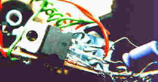
These components can be placed in the now empty casing. Lead the four wires out of the casing. One for +VCC, one for -GND and two for the turning direction. Before you close the casing you need to check if the H-bridge works. Apply a battery to the right wires and hold one of the other wires at the +VCC. The servo should turn now. And if you hold the other wire at +VCC then the servo has to turn in the opposite direction. Now close the casing again and prepare the other servo.
Frame
The width of your servos will define the minimum width of your walker body. Now you need to reserve some space between the front and rear servo to place the MicroCore, a start-up circuit, voltage regulator and the driver for the H-bridge. I use this driver because i want to disable the servo's when i start-up the MicroCore. You can draw your own PCB or use the one i have used. However this PCB isn't optimised. There are a few wire bridges needed to connect all parts.
Parts list
- IC's : 1x 74HC14, 1X 74HC139
- Capacitors : 4x 0.22uF, 1x 2.2uF
- Resistors : 3x 1M, 1x 2k7
- Diodes : 1x 1N4148
- Other : 2 IC sockets, 2x 5M vario-resistor, LED red, battery holder, power switch
Power regulator parts
- 5V - 78T05 or
- 3V - LD1117
- Capacitors : 2x 10uF/16V
The added power supply circuit is build around a voltage regulator. Because of the low power comsumption of the walker you can use a small regulator that is able to provide about 100mA. Using this power supply is optional and not required if you use the right voltage already. Please note that the pin numbers may not be correct for other type of regulators. So always check these before installing.
In the example circuit i use a 75T05 regulator with will give an output voltage of 5V. For the actual walker i used a LD1117 3V regulator. But these are harder to find. I didn't included it on the PCB but free-wired it to the frame.
Top of page
Now determine the width of you walker frame. If the width of your servo is greater then the width of the PBC then make the frame as width as the servo otherwise use the width of the PCB. Cut four pieces of PCB material as long as the width you just have determined. Now drill a few holes in them so you can connect the casing of the servo to it.
Next place the two servo's in line and the PCB in between them. Now measure the total length of it. Cut off two pieces of copper wire at this length. Solder one PCB strip at the end of the two copper wires. [see pic.] Connect the other PCB strip to the servo with a bolt/nut. Now connect the servo to the already soldered strip. Solder the other PCB strip to the copper wire. This way you know for sure that the holes in the PCB strips are aligned well. Remove the servo again. Bend the frame 30 degrees or so upwards. Repeat the same procedure for the other servo at the other end. Your frame is finished now. Adding the PCB will enhance stiffness later on.
Top of page 
Circuit
After creating the PCB for the circuit and drilling the holes its time to fill it with components. Start with the MicroCore. First solder the IC socket in its place. Next solder the capacitors that has to come at the solder side of the PCB. These are the three capacitors [0.22uF] that are placed on a row under the IC socket. Cut and bend the capacitor wires in the right shape before soldering. Next add the other components that are needed for a functional MicroCore. (see for more informtion about a MicroCore also the Z-Walker mk I page.)
Top of page
MicroCore testing
You can test the MicroCore by connecting a LED and a 2k7 resistor from one of the MicroCore outputs to GND. [pin 10 for example.] Keep in mind that the power regulator isn't installed yet. So supply the PCB with the right voltage. [3-5V] Before testing you can add the power supply if needed. If power is supplied then the LED should blink. If not then the MicroCore isn't working.
What can you do if the MicroCore isn't working?
- check the wiring
- is there a chip in the socket?
- is the chip of the right type and placed right?
- clean the solder side of the PCB with a toothbrush
- is the power connected?
- is the power turn on?
- is the LED connected right?
- did you use the right component values?
- are the vario-resistors in their middle position?
Some very obvious tips but people tends to forget the obvious. Me Included.
RemarksAs you may notice, i use a power regulator. This is due the fact i planned to operate the circuit at 3V but i use a 9V power pack battery as power supply. The power regulator is a LD1117 3.0V type. You can also use a 5V regulator but keep the operating limits of the IC's in mind when doing so. This is also one of the reasons that i place my IC's in sockets. IC sockets aren't expensive and this way you can't overheat your IC while soldering. And its easy to re-use your IC's. That is very useful when experimenting with different designs and chip types.
If you didn't add the power supply but you want to use it then you can add it now. Add all the other components and place the other IC in the socket. Place the PCB between the two copper wires of the frame and solder the PCB to the frame. Don't forget to connect the wire bridges between C1, C2 and C3. Just attach a wired from one point 'Cx' to the other 'Cx' point. Next, connect the servo's to the PCB. Supply power again and look if the MicroCore keeps running. The right behaviour should be that all processes in the MicroCore should be killed, except one. The servo's shouldn't react for a short time. The start-up circuit is finished now and will release one process in the MicroCore. By now the servo's should start turning. Watch the movement sequence carefully. The proper sequence has to be.
If this isn't correct you have to switch the two input wires of one servo. When the MicroCore is working correct then you can remove the test LED and resistor. Top of page
RemarkAfter you have the sequence correct then you can switch the input wires of one motor [most often the rear motor] and this will cause the walker to move backwards. If you do this with a reverser circuit for a short moment then the walker will move backwards. After some time it will then continue forward again.
Top of page
Legs
Adding legs to the walker is maybe the most crucial part of the whole design. Shape has a large impact on the walking capabilities of the walker. I made my front legs quiet longer and wider then the rear legs. This will lift the walker higher up with the same angle of turning by the servo. The rear legs are shorter and facing backwards so they can push the walker forward better. The long front legs are more flexible than the rear legs due to their length, which allows them to bend without deformation when the rear legs push the walker forward. The legs are made from copper wire and are bend in the right shape. I gave the legs a 'shoe' made of soft rubber tubing to add more friction. Now remove the wheel, cross or whatever sort of attachment that comes with the servo.Usually these wheels or crosses has multiple holes to connect different items. Bend the leg in such form that it will cover three set of holes. Now you can fix the leg with thin metal wire for which I used a paperclip 
Fit the leg again to the servo. Place the walker on its back and turn the power on. Watch the leg movement and try to balance the movement by adjusting the vario-resistors. The legs should turn the same angle in either direction.
However in time the legs will still show some drift and the walker will drop on its side. I did remove the end-stop in the servo's so i had to make some new end-stop on the frame. If you didn't remove the end-stop but the legs are turning to far then you can add the following. Turn the legs in their maximum position and soldered a small piece of PCB at that place to the frame. This will stop the legs from turning to far in that direction. Repeat this on the other side and other servo. After some time using these end-stops it showed that the legs are to strong and the stops started the bend also. I had to enforce them with soldering an extra copper wire between them.
RemarkOne builder suggested to place a spring between the two legs. This will act as a real muscle. I didn't try this yet but i think that it will be a good solution too. However, using end-switches will be more energy efficient and more friendly for your gears. The switch should disconnect the input wire to the servo for that direction.
Brain O.Bush, an experienced builder gave his opinion about this.
"Actually, it is more biological and if i may so mention, seemingly gives feedback. End switches seem so abrupt and discrete, which is why I did not use them - i did try however but it walked like a robot. Not like a creature."
'end quote'
Top of page
Appendix
Improvements
The following section will provide you some hints to improve your walker. Changing the gait of the walker in such way that some sort of a turn can be accomplish is possible with one of the following
Top of page
This last section will provide you with some ideas about improving your walker. First you can change the gait and the speed of the gait in different ways. It is possible to let the front or rear legs move slower. Or to say it better, let them move a larger angle. This can be done by placing a resistor in serie from the vario-resistor to GND. If you want to influence legs individually then you can change the resistor that is placed between the vario-resistor and the Schmitt-trigger [7414 chip]. There are several ways to do this. One can think of placing a resistor in serie_s_ or parallel combined with a switch. Or using photodiodes to make use of changing light conditions. A photodiode will have a high resistance in the dark and a lower resistance when light shines upon it. The BEAM Tech FAQ - section Sensors and Nv Networks can provide you more information. The picture on the left will give you some idea about what you can do. All the mentioned options are included. You don't need to use them all to get result.
Adjusting the gait
Top of page
A timerSometimes there is a need for a time delay. A timer would be very handy in such cases. It is easy to create one with a RC circuit and a Schmitt-trigger. As you may have noticed there is one Schmitt-trigger still unused. This one can be used to function as a timer. The timer will start as soon as the switch is closed and opened again. The time delay is approximately equal to 
Time [seconds] = Resistor [Ohms] * Capacitor [Farad]
The timing can also be altered with a photodiode. This will give you time delays that depend on the light conditions for example. As you may have noticed, the schematic has two outputs. One named FORWARD and one REVERSE. This schematic can be used as a timer to activate the reverse mechanism for a walker.
Top of page
Reverse Reversing a walker can be done by crossing the wires to one motor. You can do this with a DPDT relay. You need the wire the relay as shown in the reverse diagram. A relays is reliable and easy to use. But it is also power hungry and often needs a voltage that is higher then the voltage supplied to the walker. There are however
small micro relays that are suitable but they are also very expensive. A more elegant solution will be the use 4066 chip. This chip contains 4 switches [normal open]. With this chip you can simulate a DPDT relays. But more importantly, it will use far less energy to switch then a relays. A wiring schematic in the form of a PCB in included to give you an idea how to wire the chip. The 4066 is an inexpensive IC and easily available. The PCB is shown with the copper side facing up.
Top of page
Newbie guide to electronics
Newbies in electronics can have difficulties with the component values and descriptions. This section hopes to give those people some guidelines for resolving these problems.
Basics
The most often used terms in electronics are voltage and current. To give you a metaphor for this you can think of a river. The voltage is the length of the river and the current can be seen as, well.. the current of the river. This current is due the difference in height between the start and end of the river. One law you have to remember is law of Ohm. It is a simple law.
Voltage = Current * Resistance
or U = I * R
Where voltage is in voltage [V], current in Ampere [A] and the resistance in Ohm.
To make it easier for you to make conversions i will provide you [literally] a rule of thumb.
Voltage [V]
-------------------------------
Current [I] * Resistance [Ohm]
Now just place your thumb over the unknown value and you will see what you have to do to find the value. For example. If you want the know the resistance then you have to divide the voltage by the current.
Numbers can become quiet large in electronics. To prevent writing many zero's they use often different names. The following names are used.
Value, milli-, micro-, nano- and pico-
Example: Farad [capacitor] Farad, milli Farad [mF], micro Farad [uF], nano Farad [nF], pico Farad [pF]
Every step is 1000 smaller like 1 Kg is 1000 Grams.
Top of electronics guide
Resistors
 Symbol ---/\/\/\/\---- or ------ ---| |----- ------A resistor can be seen as a dam in a river. Water will have more difficulties to pass this dam. In a resistor this will result in the generation of heat.
Resistors come in standard values to choose from. The value of a resistor can be found with the help of a colour table. The resistor has a set of coloured rings that will tell you its value.
First ring : First number
Second ring : Second number
Third ring : Number of zeros to add
Fourth ring : Tolerance [quality of the resistor. Mostly 5%]
1 Brown                Examples:
2 Red                  4700 Ohm                   1 000 000 Ohm
3 Orange               Yellow Purple Red          Brown Black Green
4 Yellow
5 Green
6 Blue
7 Purple               Brown Black Brown          Red Red Red
8 Grey                 100 Ohm                    2200 Ohm
9 'White'
0 Black
Values are often written as 10K, 1M or 4K7. This means in this case 10.000, 1.000.000 and 4700 Ohm. The 'K' just stands for Kilo and tells you that there is a factor 1000 there. The 'M' stands for mega and adds another factor 1000
Top of electronics guide
Capacitors
 Symbol || ---||--- ||A capacitor can have more functions but one of them is to store some energy in them. They act like a bucket. You can fill them with energy and drop the contents back when you need it.
Values are often written as 10N or 2N2. This means in this case 10.000 and 2200 nano Farad. The 'N' just stands for nano. Small capacitors can have only numbers on them like 104. The first two digits is a number and the third digit tells you how many zeros you must add. In this case its four. The correct value of this component is 100 000 pF. [note: 100 nF or 0.1uF is also correct]
Top of electronics guide
Diode
 Symbol |\ | ___| \|___ | /| |/ |Diodes are the passive one-way locks in the river. Water can flow through them only in one direction. And only when there is enough difference in height [voltage].
Knowing this you may notice that a diode needs to have a direction to function. To show this there is a small mark at the casing. Normally this is a ring. For LED this isn't the case. You have to look inside and see the small plates. The one with the largest plate is the side where the 'ring' would be.
Top of electronics guide
Transistor
 Symbol | /c c = collector ___|/ b = basis b |\ e = emitter | \eThese are the active locks in the river. They have a lock gate that can control the flow through them. They can also act like a switch. With a little current they can be opened and let a strong current pass. In the symbol there is also a arrow that will tell you the direction of flow. There are two basic transistor types namely; PNP and NPN. This is because the way how they are build internally. A PNP has a symbol with the arrow pointing inwards and a NPN transistor has a arrow pointing outwards.
Top of electronics guide
IC
 Symbol An IC doesn't have a universal symbol. It all depends on its use. A few examples are shown here. |\ +---+ ___| \___ -| & | | / -| |- |/ +---+A little box that contains many small components as above. A complete circuit can be inside the black plastic casing. They have often 8, 14 or 16 pins. They are used for many purposes. The casing has a small notch on top of it or carved out of it. If you look at this mark and holding the mark on top then the first lead on the right side will be pin number one. Counting the pins downwards and continue at the first pin at the bottom at the other side.
A more detailed guide to electronics for beginners and advanced can be found at this site Electronics for beginners
Or the Electronic guide for dummies of Ben Hitchchcock
Top of electronics guide
Top of page
Thanks to:
Michael at JClark76@compuserve.com for spelling and missing details.
Todd Cottle at cottle@q-com.com for comments and corrections
Brian O. Bush at bbush@gensym.com for text corrections and remarks.
Eric at ericysh@pl.jaring.my for PCB comments and addittions for beginners.
Benjamin Edward Hitchcock at beh01@uow.edu.au for providing electronics insights
Victor at T.S.V.TEE@Bradford.ac.uk
Top of page
Copyright © 1998, A.A. van Zoelen. All rights reserved.
A.A. van Zoelen / vsim@mail.com
Updated: 26 Oct. 1999