|
|
|
B E A M - R o b o t i c s
Biology - Electronics - Aesthetics - MechanicsZ-Walker mk III

Project status : Finished
Last update : 18 April 1998
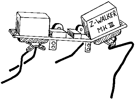
I had the need for a walker-based test platform to try out my ideas. For this i wanted to create a very basic four-legged walker. The aim of the design was to create a walker that can be altered, robust and durable.
My goals
- Robust
- Not expensive
- Battery powered
- Easy to build
- Quick to make
To create such a walker i need to use comfortable priced and available parts. Just in case something got damaged. The frame must be able to hold a variety of motors. I choose for a servo as motor. I use two modified heavy-duty servo's and use these for driving the robot. These servo's are also the most expensive parts of the whole design.
GRAPHICS ASCII Block diagram of design +-----------+ +----------+ | Power |-- + | Modified | | regulator | | Servo | +-----------+ +----------+ | | | === | | +-----------+ +-----------+ +-----+ | |---| | | PNC |---| MicroCore | | Z-bridge | +-----+ | |---| | | +-----------+ +-----------+ | | | | +-------------------------+ | | | | +----------+ | Modified | | Servo | +----------+ Fig. 1
Parts list
- IC's : 40106, 74F139, LD1117-30V
- Transistors : 8x PNP, 4X NPN
- Capacitors : 4x 22nF, 2x 0.1uF, 10uF/16V
- Diodes : 5x 1N4148
- Resistors : 2x 5M vario, 1M, 4x 47K
As you may notice, i use a power regulator. This is due the fact i planned to operate the circuit at 3V but i use a 9V power pack battery as power supply. The power regulator is a LD1117 3.0V type.
The walker has proven to be quite good indeed. It has little problems with walking over a carpet. It can make a turn on the spot or turn around in a circle with a diameter of about 40cm. Reversing the walker by connecting the rear motor the other way round made it reverse. All these functions where tested by one time hard-wiring. I have tried a few leg design on this one also. Its quiet interesting to see how the performance change as you change the shape of the legs. For example if the walker goes reverse then it will move difficult if your legs are optimise for maximum forward thrust.
Conclusion:
This test platform has proven to be a right shot. It holds up the punishment it has given and it's still operational. I hope to bring you the plans for building a walker for your own based on these findings. Model IV will probably a design that can be build as a kit.
Copyright © 1998, A.A. van Zoelen. All rights reserved.
A.A. van Zoelen / vsim@mail.com
Updated: 26 Oct. 1999