|
|
|
B E A M - R o b o t i c s
Biology - Electronics - Aesthetics - MechanicsPhoton mk II
Project status : Finished
Last update : 20 Jan. 1998After a day of frustration i decided that i needed some form of success. All day i had to deal with problems like, parts missing, defect parts, circuit malfunctions. I planned to build a solar roller. I searched through my parts box and found all the parts to make a solar roller. I started to build one.
I started with these parts
Solar engine
- 1x BC549B [NPN]
- 1x BC557 [PNP]
- 1x FlashLED red 3mm
- 1x 4K7
- 1x 4700uF
- 1x Solarcel from a calculator
Wheels from a walkman
- A large flywheel incl. bearing
- Small rubber wheel incl. frame
Motor
- Bertsch micromotor. One from a ruined gearbox.
- Rubber snare
Other items
- Tin can.
- Glue
- Tape
- Styrofoam.
- 1x Small parker screw.
- 1x Fiber ring.
Tools
- Solder iron 18W.
- Clothes-peg
- Knife
- Plier
- Cutter
- Scissor
- Screwdriver
- Grindstone
- Digital multimeter
- Coffee
Where to find these items?
- Wheels, motor, screw, snare, fiber ring, transistors, resistor
- All parts from a walkman, garage sale.- Tin can.
- Grocery store, food container, metal strip from battery holder.- Styrofoam.
- BigMac container, food store. Its often below sliced meat.- Solarcel
- Calculator, garage sale.- Capacitor, flashLED
- Electronic parts store. Garage sale. Old television or radio.- Coffee
- Supermarket.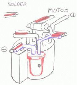
irst i made the solar engine. Just the simple one as stated in the BEAM FAQ. I soldered some leads on the solarcel i hooked the solarcel on the circuit for testing. The solarcel charged the capacitor and triggered. The motor was spinning, so i was pleased with the result.
F
To design the frame i needed a few numbers. I placed the snare around the flywheel and the motor axe and i measured the distance between them. Then i cut a small strip (5mm width) from the tin can and at the end i curved it a little. I took the bearing from the flywheel axe, placed it in the curve and solder it fixed in that position. I made a twist off 90 degrees in the metal and measured the place where the motor had to come. The motor has a rectangle piece sticking out on the back side. Below of it there is a hole in the cover plate. I saw that the plastic casing underneath had a slightly smaller hole. That would make it perfect to fit a parker screw. I drilled a hole in the metal plate and screwed the motor to the frame. By keeping a little space between the frame and the rectangle piece on the motor i am able to turn the motor slightly. Becauseof this i can change the force put on the snare. The solar engine is then soldered to the lead pads of the motor. And the capacitor is glued to the bearing. Making it more rigid as a whole.
As work progress a disappointing feeling is growing more and more. This thing won't be able to steer!. Also it stands very unstable on its two wheels. To give it more stability i need to add a third wheel. That disturbs me. I went again through my part box and yes, i had enough parts to build a second solar roller. If i combine these two then i can make a photovore, or at least something that can steer and is more stable. I finished the second solar roller and tested the solar engine. All worked fine. Next the two solar rollers had to be glue together to make it one little bot. With some 'plates' of Styrofoam i added some struds to make it more stable and rigid. Remark: first try the glue on a little piece of Styrofoam to see if its not melting... The axes of the flywheel where to long now. I had to shorten them. These axes are really hard!! I had to use a grindstone to cut them. So be warned. The solar roller is now standing on its wheels and looking great. But will it also perform great? Seeing it standing there gives me already some satisfaction. Now all i have to do is adding the solar cells to it. I placed the two solar cells at a angle to each other and a little upwards, facing in the driving direction. Again i used Styrofoam to make a little frame for it. This frame i glued at the sides of the motors. Connected the wires. The left solarcel feeding the right solar engine and vice versa.
Tension rise as i went off to the sunlight. Patienceless i waited for the solar engines to fire and that the roller will zoom away. But.. I heard something but i didn't saw a thing moving. What happened? One solar engine triggered below 2V. I hadn't checked it. So it had far to less energy when it fired. I added another diode in line with the FLED. Test number two. Again i am waiting. And yes it moved a few millimetre. But more strangely it turned on the spot! The cause of this was that i mirrored the second solar engine but i wired the motor in the same way as the other solar engine. I had to crosswire one motor to make is turn in the same direction as the other motor. Test number three. The roller is moving now in right direction. But only a very short distance. Starting a motor consumes the biggest part of the stored energy. After that there isn't much energy left to keep the motor turning. To solve this i can enlarge the storage capacitors. But this will give me a different problem.
When i enlarge the capacitors of the solar engines i will have more energy to spend. This will result in a longer distance to travel. But if the other wheel is standing still then the path of this movement will be an arc or even a full circle. And that isn't what i have in mind. To overcome this i need to add some sensors that 'sees' that the roller is travelling straight to the light. And if this happens then i need to activate the other motor. If this other solar engine isn't charged enough then it has to use the energy of the other solar engine. To accomplish this i need to redesign the complete solar roller. A few fixes aren't enough to do it. Besides that, starting from scratch is better. I had my good time with this one and i learn a lot from it.
PRO's CON's HINTS Simple.
Easy to build.
No critical parts.
Quick to build.
Fun to build.
Not a 'off the shelf' design.
Design depends on
available parts.
Errors will have
major effects on design.
Watch the motor connections.
Use larger capacitors.
Use a grindstone to
shorten the axes.
I hope this page will help you improving your own building.
Bram
Copyright © 1998, A.A. van Zoelen. All rights reserved.
A.A. van Zoelen / vsim@mail.com
Updated: 26 Oct. 1999