|
|
|
B E A M - R o b o t i c s
Biology - Electronics - Aesthetics - MechanicsPhoton mk I
Project status : Open
Last update : 15 Jan. 1998
I like walking robots more then wheeled robots but for this one i decided to use wheels. I've seen the pages of Steven Bolt and his photovore using clocks. That made me decide to build a photovore of my own. As usual i gave myself a set of goals to achieve. This is also helpful to keep the project going and reasonable. Also will it give you a moral boost if you can meet one or more of your goals.
This is what i had in mind:
- Two wheels
- Clock driven
- Light seeking
- Solarized
- Avoiding obstacles
- Movement in a straight line.
As you can see they are not that extraordinary goals. Movement in a straight line is possible by placing one clock with its wheel to the outside and the other clock with its wheel to the inside. So if the clocks are turning then both wheels will push forward. But... it looks terrible and the complete design is out of balance. There had to be a better solution for this.
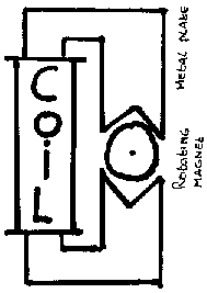
The clocks turning direction is determined mechanically, but i didn't see how. Till Mark van Dijk told me how he was able to reverse the turning direction of the clock. But it could only be CW or CCW and it would stay this way.This is the solution
Changing the turning direction
GRAPHICS ASCII What i did was to expand the gap between ONE plate and the magnet a little with a file. And i bend the plate a little upwards so it wouldn't be inline anymore with the other plate. This made the clock turn counter clockwise
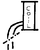
The next problem was, how must i drive a stepper motor? Even worse... What is a stepper motor. Both questions where solved with a search on the web. There is really good material about stepper motors on the web. In short a stepper will rotate if you feed it with a pulse. I guessed that a BiCore should do, because it also generates pulses. I made one on breadboard, hooked a prepared (see fig. 2) clock to GND and one output of the BiCore. The magnet is just wobbling now. I remembered a picture where a stepper was hooked to a H-bridge, and when i think about it it sounds reasonable. One pulse will turn the magnet a little bit and the next pulse will take it over and take it further, ect. I expanded the BiCore with a H-Bridge and now the magnet is turning nicely. I am to let the second hand spin up to 16 RPM.
A Z-bridge is also quiet capable of driving a stepper.
GRAPHICS ASCII Preparing a clock +---+ | | | C | | o | | i | | l | | | +---+ | | a | +----//--- +-----//---- b Fig. 2By changing the 1M resistors in the BiCore i could change to RPM's of the clock. The complete design drained 15mA. This is quiet high. With some current limiting resistors the current dropped to 5mA. The clock is now merely ticking. The second hand didn't give enough torque anymore. After raising the current to 10mA the second hand had again enough torque to move the clock casing. This current drain is very high. In a conversation Steven Bolt pointed my at the fact that the duty cycle that i use must be almost 100%. He must be right because both the two states the BiCore could have drive the stepper motor. I had to change the duty cycle. By adding one extra NV neuron i am able to change the duty cycle. Two NV's firing very short pulses and the third is used as a time delay. An extra advantage of this approach is that i still can drive two clocks with one chip.
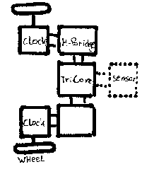
GRAPHICS ASCII Block schematic -------- | wheel | -------- || +-----------+ +----------+ | |---| | | Stepper 1 | | H-bridge | | |---| | +-----------+ +----------+ | | | | +----------+ ........... | |..... . | TriCore | . Sensors . | |..... . +----------+ ........... | | | | +-----------+ +----------+ | |---| | | Stepper 2 | | H-bridge | | |---| | +-----------+ +----------+ || -------- | wheel | -------- Fig. 3
The design so far, build in parts and tested. The sensors hasn't been tried yet. Movement cq. driving around isn't tried also. Hope to do this in the near future.Wheels
I bought two wheels, 5 cm in diameter and with air tubes. These are very light wheel. I took the second hand and i cut off the needle. The remaining part i glued to the wheel at the place where the axe would enter. The wheel can be mounted directly to the clocks this way.
Sensors
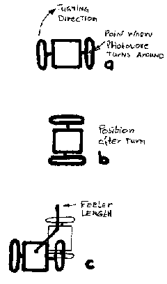
For light detecting i plan to use LDR's. The feelers are a different story. Since the steppers can move backwards there is no way to move away an obstacle by reversing its motion. The photovore has to detect obstacles that are still outside its turning circle. This implies the use of long feelers in the case of wire feelers. They must cover atleast the radius of the turning circle of the photovore. By turning only one wheel is must be able to go around an obstacle. The photovore can avoid most obstacle this way but can get stuck in a corner. If the photovore gets stuck then he will be able to signal this by sounding an alarm signal. A signal you can't ignore, the music of a happy birthday card.
GRAPHICS ASCII Feelers _. /| Turning direction | _ - | | +---+ | | | |=| |=|+|<-Point where then | | | | | | photovore turn - +---+ - around A ----- | | ----- | Position after +---+ movement | | | | +---+ | ----- | + | ----- B /-> ...|... / . | . Dotted figure Feeler ...|... is the location length | after movement ..|.. . | . . | . ./... - / - | | +---+ | |.. | |=| |=|+| . | | | | | |.. - +---+ - C Fig. 4Fig. 4 A shows the starting position. The photovore will drive only his left wheel and the other wheel will stand still. The photovore will now turn clockwise to the position as seen in fig. 4 b. The feeler has to reach outside the area that is covered by turning the photovore. Fig. 4 c shows the distance it should cover atleast.
To do:
Making a decision about the size of the solar cell to use. Also the I still haven't a good design for a solar engine to power the electronics and i have to try a new SE design first. These two decisions are related to each other. After i have determined the size of the photovore i can think about its feelers.
I hope to expand this page soon.
Bram
Copyright © 1998, A.A. van Zoelen. All rights reserved.
A.A. van Zoelen / vsim@mail.com
Updated: 26 Oct. 1999